PWM
Table of contents
- Overview
- S32K312 Configuration
- Frequency and Duty
- Duty Calculation in C
- Runtime Update
- Complementary Output and Dead Time
- Measurement
Overview
PWM은 period와 active time으로 출력을 제어한다. Frequency·duty뿐 아니라 polarity·edge alignment·update 시점·fault 시 output 상태를 함께 설정한다.
S32K312 Configuration
사용 가능한 timer/PWM IP, channel, pin mux, output polarity는 S32K312 패키지와 설치 RTD의 예제로 확정한다. 다른 S32K 제품의 timer 이름·register 주소를 그대로 가져오지 않는다.
| 항목 | 실무 설정 |
|---|---|
| Clock | Functional clock source·divider·gate를 확인하고 저전력 복귀 후 변화를 검증한다. |
| Mode | Edge-aligned와 center-aligned를 구분한다. 동일 MOD에서 frequency가 같다고 가정하지 않는다. |
| Period | Counter의 endpoint 포함 여부와 실제 divider 값을 기준으로 계산한다. |
| Duty | Active polarity와 compare 동작, 0%·100%의 특수 처리를 확인한다. |
| Update | Shadow register에 쓰고 reload 시점에 반영하여 짧은 glitch를 피한다. |
| Output | Pin mux·pad·driver enable·fault override·부팅 시 안전 레벨을 정의한다. |
Frequency and Duty
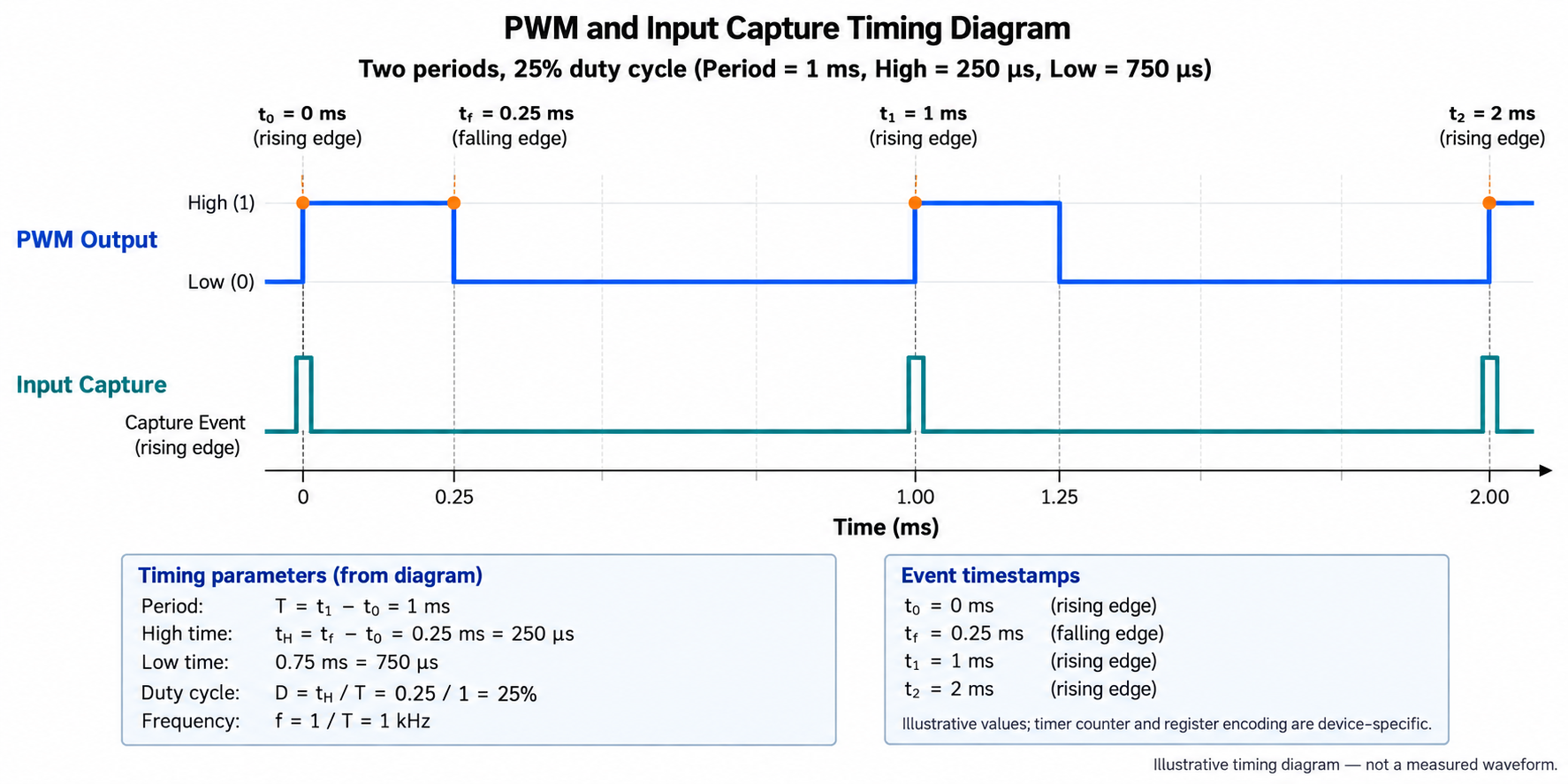
상향 counter가 0..MOD를 포함하는 edge-aligned 모델이면 period tick=MOD+1이다. 예를 들어 f_input=80 MHz, divider=80이면 tick=1 μs이고 MOD=999이면 1 kHz다. 250 tick 동안 active이면 duty=25%다. 이 모델을 center-aligned나 다른 reload 정의에 그대로 적용하지 않는다.
Duty Calculation in C
아래 함수는 active tick을 계산할 뿐이며 실제 register 값이나 0/100% 출력 모드를 결정하지 않는다. Driver adapter가 endpoint 동작과 polarity를 처리해야 한다.
#include <assert.h>
#include <stdbool.h>
#include <stdint.h>
#include <stddef.h>
static bool active_ticks(uint32_t period, uint32_t permille,
                         uint32_t *active) {
    if (!active || period == 0 || permille > 1000) return false;
    *active = (uint32_t)(((uint64_t)period * permille + 500) / 1000);
    return true;
}
int main(void) {
    uint32_t n;
    assert(active_ticks(1000,250,&n) && n==250);
    assert(active_ticks(1000,0,&n) && n==0);
    assert(active_ticks(1000,1000,&n) && n==1000);
    assert(!active_ticks(0,500,&n));
    assert(!active_ticks(1000,1001,&n));
    return 0;
}
Runtime Update
Period와 compare를 함께 변경할 때 어느 값이 먼저 적용되는지 확인한다. 더 작은 period로 변경하면서 이전 compare가 period를 넘지 않게 구성한다. 필요한 여러 channel은 지원되는 synchronization/reload mechanism으로 함께 갱신한다.
Complementary Output and Dead Time
Motor·half bridge처럼 complementary output을 사용하는 경우 두 스위치가 동시에 켜지지 않도록 dead time·interlock·hardware fault path가 필요하다. Dead time 지원 여부와 단위, gate driver 지연을 확인한다. 단순 GPIO 반전이나 ISR 지연으로 안전한 complementary PWM을 구현했다고 가정하지 않는다.
Measurement
Scope로 frequency·active width·jitter·update glitch·0/100%·start/stop·fault 상태를 측정한다. LED 밝기는 duty에 선형으로 보이지 않을 수 있으며 gamma/전류 제어는 별도 요구사항이다. Input Capture로 되읽을 때는 출력 검증 경로와 독립적인 clock 오차도 고려한다.